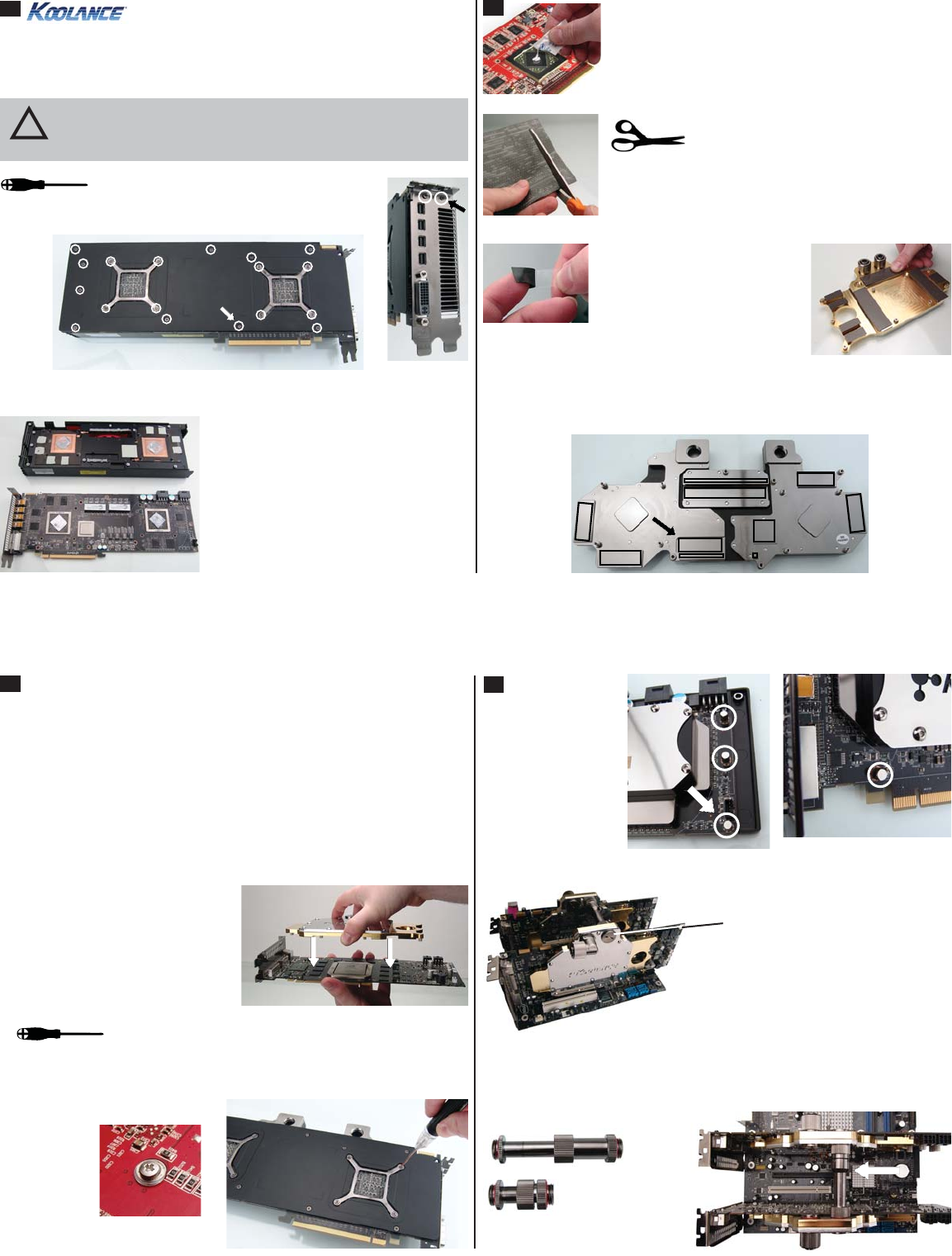
All heat sink assembly screws should be
removed. There should be about 18 of these
on the back of the video card, and 2 more on the L-bracket.
NOTE: The video card should be removed from the chassis in order to install this
cooling device. Most cards using the VID-series blocks are disassembled the same
way, although heat sink assemblies of any given model can vary.
VID-AR699 Installation Guide v 1.0
1
HD 6990 Disassembly Screws (Bottom and Rear L-Bracket)
CAUTION: Removal of the original heat sink or liquid cooling may void
your manufacturer’s hardware warranty. Please consult the manufac-
turer if unsure, and keep all original parts in case of a return/RMA.
!
Socket plugs are included with the VID
coolers which must be placed opposite
the desired nozzle locations.
Connecting Multiple VID Coolers
When connecting multiple VID coolers, Koolance offers an optional direct-connect
nozzle. This minimizes liquid routing while avoiding potential conflicts with hardware
in between the video cards.
Optional Two-Three Slot (CNT-VDA34) and
One Slot (CNT-VDA2) Video Connectors
G 1/4 BSP inlet/outlet nozzles can be
screwed into the top or bottom side of the
cooler, as long as coolant flows from one half
to the other (left to right or right to left).
4
4 thumb nuts are
supplied to take the
place of empty screw
hole positions on top
of the video card.
With all screws removed, carefully remove
the top heat sink. Original thermal paste may
present resistance during removal.
Unplug the heat sink fan wire. Remove the
original RAM thermal transfer material (front
side only), and wipe any residual thermal
material from the main GPU chipsets.
Basically, any area of the video card in contact with the original heat sink will need
new heat transfer material. Place heat transfer pads on the corresponding areas
of the Koolance water block.
3
Place the Koolance block onto the video
card so the mounting screws will align.
2
Tighten each screw on the reverse side of the card. If the
original video card screws do not fit, use the Koolance-
supplied screws and plastic insulating washers. Original video card rear brackets
or back plates can be used if they still allow the water block to be mounted.
Koolance-Supplied
Screw and
Insulating Washer
Gray thermal pads have plastic
film on both sides that must be
removed before application. Pink/
white thermal pads have plastic
film on one side (white) that must
be removed. Do this after cutting
the proper shapes.
The thermal pad sheet should be cut into
pieces required for your video block contact
areas. Please use the diagram included
with your water block to determine the approximate sizes
needed. Koolance heat transfer pads have different
thicknesses (gray = 0.5mm, pink/white = 1.0mm).
Thermal paste is only required on the main GPU’s. The
other areas will utilize the included heat transfer pads.
Spread thermal compound on both GPU’s thinly and evenly
using the included paste packet, or a piece of thick paper
(such as a business card).
Multiple types of heat transfer pads are included with some Koolance blocks.
You might not require both (check the pad diagram). This is done because card
manufactures change the component height tolerance from time to time. After
completing video block assembly, it’s recommended to remove the block temporarily
to check thermal paste and pad impressions for good component contact:
• If the GPU area paste is not evenly disrupted, thinner thermal pads may be
needed in corresponding areas to improve GPU contact.
• If thermal pads have no chip indentations but the GPU paste looks good,
thicker thermal pads may be needed to improve contact in those areas.
 (1 pages)
 Manymanuals.com
 Manymanuals.de
 Manymanuals.fr
 Manymanuals.it
 Manymanuals.pl
 Manymanuals.cz
 Manymanuals.es
 Manymanuals-pt.com
Commentaires sur ces manuels